I love graphics programming. Don’t get me wrong – writing, say, a stored procedure for a database is perfectly respectable and responsible work, but there’s nothing like colored pixels on the screen to make me say “Woo-hoo!”
I recently started re-educating myself on OpenGL ES 2.0 in anticipation for a project I’m planning. I’ve done work with OpenGL ES 1.1 before, there are significant changes in 2.0. As many of you may know, the biggest difference between OpenGL ES 1.x and 2.0 is the “programmable pipeline.” In 1.x, the methods via which shading was performed was pre-determined – you provided various high-level information like light positions, etc., and the graphics engine took over from there. By having a fixed pipeline, the graphics drivers and the GPU could be made much simpler, which is (or was) appropriate for the lower-cost GPU’s in mobile devices. Simple, but not powerful. In OpenGL ES 2.0, those restrictions are gone, and you’re now allowed to do a whole variety of things in the graphics pipeline that you couldn’t do before.
But with great power comes great responsibility – if you use 2.0, you are completely responsible for defining some critical aspects of the pipeline by providing two “shaders,” each of which is a small (or not-so-small) program in and of itself. Writing shaders isn’t necessarily difficult, but they can be a little daunting to the beginner. The biggest issue that I had in coming to grips with shaders is that I didn’t have the context for how they fit into the grand scheme of things – I found lots of example shaders “out there,” but very little explanation for exactly what they were doing. Finally, I had one of those “a ha!” moments, and it all came into perspective. So, Gentle Reader, to save you the same pain, here’s a bunch of background on shaders.
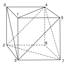
So let’s assume that we’re going to draw the infamous cube as part of an OpenGL program:
There are a number of overall steps that are involved, the most important of which are shown in the following diagram:
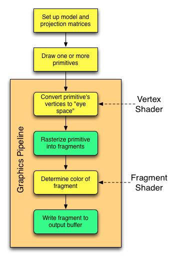
- Before we actually draw anything, we set up the “model” matrix, which tells OpenGL where our cube is going to be positioned in 3-space, how it’s oriented, etc. We also set up the “projection” matrix, which defines where our “eye” is going to be in 3-space, and where it’s looking. (All this assumes a 3-D perspective view. If you’re doing 2D programming, the shader principles are the same, however.)
- We request that OpenGL draw one or more primitives. A “primitive” is a triangle, line or point – here we’re going to focus on triangles. Using the various techniques available via the OpenGL API, we can request more than one primitive be drawn with a single call – right now we’re not worried about the exact details of how the request is made.
Here is where the graphics pipeline starts. It’s important to understand that the steps within the pipeline are (effectively) performed once for each primitive in the system. In reality, there are a whole bunch of optimizations that the pipeline can make, but conceptually the pipeline processes each primitive in sequence.
- The first thing the graphics pipeline needs to do is it needs to convert the vertices for each primitive into “eye space.” This essentially figures out what the primitive “looks like” from the point of view of the “eye.” This is the job of the vertex shader. At a very simplistic level, you can consider the input to the vertex shader to be the “world” position of a vertex, and the output to be the (x,y) screen coordinates at which it will appear. (That’s oversimplified, since it’s actually returning a 3D vector, but it’s the basic concept.)
-
The next thing that the pipeline needs to do is to “rasterize” the primitive. Assuming that we’re drawing a triangle to the screen, this means figuring out the set of screen points that the triangle covers. You can think of this as (essentially) going through the following steps:
- Determine the “top” and “bottom” vertex to figure out the top and bottom lines on the screen overlapped by the triangle.
- For each line on the screen between these, determine the left-most and right-most pixel for that particular line by computing where the bounding lines of the triangle intersect the scan line of the screen.
The above is another over-simplification, but this isn’t really our concern right now.
- For each of the pixels on the screen that fall within the triangle, determine the color of that pixel. This is the job of the fragment shader. The fragment shader’s output is a color.
- Taking that color and writing it into the output buffer so that it will actually be shown on the screen.
The operations colored yellow are the ones for which we’re responsible for writing code. The other operations are taken care of by the pipeline.
As I mentioned, there are many optimizations. Just for the purists among us, I’ll mention a few of them:
- As you can see from the first diagram, each of the eight vertices in the cube is shared by 3 or 4 triangles. If we are drawing by providing OpenGL with vertex indices to define each primitive in the overall shape, as opposed to sending it raw vertex lists, OpenGL can process each vertex through the vertex shader once, save the result for each and then use that transformed result for each primitive that involves that vertex. This is an optimization that needs help from us, as it depends on us sending OpenGL the data in the correct way.
- Once the primitive has been converted to “eye space,” the pipeline may realize that the primitive is not in view – it’s outside of the area that the “eye” can see. In this case, the primitive can be discarded. The primitive can also be discarded if “back face culling” is turned on and its facing away from us. This saves having to rasterize and shade the primitive.
- Even if a portion of a primitive is visible within the “eye space,” not all of it may be. Thus, only that portion of the primitive that is actually visible needs to be run through the fragment shader.
- If depth buffering is enabled, the pipeline may be able to determine that a particular pixel is obscured by an intervening primitive. In this case, there is no need to call the fragment shader to determine its color, since it won’t appear on the screen. Ditto if a pixel is being excluded by a stencil.
This is far from a complete list, but the basic idea is to abort processing as soon as possible. Although the vertex shader is called once per vertex per primitive, the fragment shader is potentially called once per screen pixel for every primitive. That’s a lot of processing, so it’s obviously desirable to reduce the number of calls where possible. The shaders (and the fragment shader in particular) are also highly parallelized in most GPU’s, so that the GPU can be banging away at a whole bunch of screen pixels simultaneously.
OK, back to shaders. Let’s look at a little shader terminology:
- A uniform is essentially a “global variable” which contains information that is constant for the entire time a particular primitive is being processed. The value of a uniform may change from primitive to primitive, but the vertex shader and the fragment shader will both see the same values when they’re crunching on data for a particular primitive. Uniforms are inputs to both the vertex and fragment shaders, and are read-only from their point of view.
- An attribute is a property of an individual vertex. The position of the vertex in 3-space is almost invariably provided as an attribute, but one can provide other attributes as well. This includes things like the color of the vertex, the surface normal vector at that point, the texture coordinate for that vertex, etc. Attributes are inputs to the vertex shader, and are read-only from its point of view. Fragment shaders can’t see attributes, at least not directly.
- A varying is a value that is an output from the vertex shader, and an input to the fragment shader. The significant point is that the vertex shader outputs such a value as it appears at that vertex, however the fragment shader will get the value as it appears at the particular pixel being computed. The rasterizer sits between the vertex shader and the fragment shader, and it interpolates
varyingvalues. Thus, if we define a “color” attribute for each vertex, the vertex shader will output the color at each vertex, however the fragment shader will see a value that is smoothly interpolated between those values – one-dimensionally in the case of a line primitive, and two-dimensionally in the case of a triangle primitive. If the vertex shader has anattributethat it wants to make available to the fragment shader, it must copy the data from itsattributevariable to avaryingvariable, since the fragment shader can’t seeattributes.
Finally, why “fragment?” Why is it called a “fragment shader” and not a “pixel shader?” There are two fundamental reasons. One is kind of picky – because of features like stencils, it is entirely possible that the value output by the fragment shader may never actually be written to a pixel in the output buffer. Depth buffering, “eye space” truncation, etc. could also cause that, but of course most graphic pipelines are designed so the fragment shader isn’t even called in those cases.
The second reason is more real. Many OpenGL implementations provide support for anti-aliasing to cut down on “jaggies” in the output image. One of the most common way of doing this is to effectively render the screen at a higher resolution and then “average things down.” Thus, it is quite possible that the pipeline might call the fragment shader at resolutions that are “finer” than an individual pixel, and then combine multiple results to compute the final pixel value. The means via which this is done (or whether it’s even supported) are specific to the particular graphics pipeline – your shader programs never (well, almost never) know that it’s happening. (For the pedantic among us, the shader language does define special variables that would allow a fragment shader to determine that “sub-pixeling” is going on, but it’s very rare to need this information.)
Thus, when you write your vertex shader, you will:
- Define one or more
attributevariables so that you can get per-vertex information. - Optionally, define one or more
uniformvariables to accept non-vertex information directly from your application. - Optionally, define one or more
varyingvariables to arrange for interpolated information to be provided to the fragment shader. - Write the code that will take the
attributes anduniforms, combine them, and write pass them back to the graphics pipeline. Specifically:- For each processed vertex, you must write to a special pre-defined variable named
gl_Position. The value written will be the vertex position transformed into “eye space.” - If your program is using point primitives, such as for a particle system, you will also write to a pre-determined variable named
gl_PointSizeto define the size of the primitive. (The farther away the particle is, the smaller it should (usually) appear. - If your program defines
varyingvariable(s), you must also write a value to each of these for each vertex.
- For each processed vertex, you must write to a special pre-defined variable named
OpenGL provides you several API calls that then allow you to specify the values of uniforms and “wire up” values from your vertex data into the vertex attributes.
Similarly, in your fragment shader, you will:
- Optionally, specify the
varyingvariables that are output by your vertex shader. You do this by repeating the exact same variable definition you made in your vertex shader. The pipeline will “wire up” thevaryings by name. If you define avaryinginput in the fragment shader that isn’t defined in the vertex shader, Bad Things will happen, since you’ll be dealing with undefined data. (Your OpenGL system may actually refuse to use the shader.) If you define avaryingin the vertex shader that isn’t used in the fragment shader, that’s OK, although you may be doing unnecessary work in the vertex shader. - Optionally, define one or more
uniformvariables to accept non-vertex information from your application. These don’t necessarily have to be the same set as used by your vertex shader – you can have uniforms that are only used by the fragment shader. If you want the two to share auniform, however, you should declare it identically. - Write the code that will take the inputs and compute the color for the fragment. This color must be written to a pre-defined output variable named
gl_FragColor.
Once you have a vertex and fragment shader, you then:
- Provide the shader to OpenGL:
- Load the shader’s source code into a string in memory. Sometimes people define the shader program directly as a string within their source code, other times they’re loaded off disk or whatever.
- Give the source to OpenGL
- Ask OpenGL to compile the shader
- Link the two shaders together into an OpenGL “program.”
- Tell OpenGL to use the program for the graphics pipeline.
In most implementations, you can have multiple programs defined within OpenGL at one time, and can change the active program at any time. Thus, it is quite possible to draw some objects using one program and others using a different one. You might do this, for example, if some portions of your scene required different lighting effects from others. The number of simultaneous shaders or programs is a function of the amount of program memory provided by the GPU or its drivers. Switching programs isn’t something that should be done with abandon, however, since there is a cost to this in terms of the GPU pipeline.
Some OpenGL implementations allow you to precompile shaders and load the compiled binary. There is no global binary standard, however, so most portable applications compile their shaders at runtime.
I mentioned before that OpenGL provides you the means of “wiring up” attributes to vertex data, and to specify the values of uniforms. This is actually done at the “program” level, which makes sense since that’s where you’d have the full list of uniforms – the vertex shader’s plus the fragment shader’s. As with many OpenGL-side items, the attributes and uniforms are specified by ID’s, which are GLuint variables. There are two ways of doing this:
- You can tell OpenGL what ID you want to use for each item. To do this, you provide each item’s name, and the ID that you want to assign.
- You can let OpenGL assign them automatically, and then ask OpenGL what ID it has assigned to each item – again, by name.
-
From what I can tell, there’s no particular reason to choose one versus the other from an efficiency point of view. If you do choose the latter route, however, you want to retrieve the information and cache it after you link the program – asking OpenGL for the values during actually drawing is not efficient, since like most “get functions,” this usually requires OpenGL to do a pipeline flush before it can return the value.
Given that you have obtained or set the ID for a uniform, setting its value is straightforward – there are a whole collection of glUniformXXX methods that allow you to set the corresponding value whenever appropriate in your drawing code.
Handling vertex attribute assignment is almost as straightforward – you call one or more of the glVertexAttribXXX family of functions for each attribute. This allows you to specify where OpenGL can find the data for the particular attribute from among the data you’re asking it to draw. You also have to call glEnableVertexAttribArray at some point to enable a particular attribute – they’re disabled by default. This can be done once as part of setting up the program, but it’s a lightweight operation, so it doesn’t hurt to do it multiple times, and it could save you a lot of head-scratching if an attribute somehow became disabled.
Hopefully this provides you with a better context as to how shaders fit into the grand scheme of things. I plan subsequent posts in which I’ll show some examples of shaders and how to use them.