In a previous post, I talked a bit about the context in which OpenGL ES 2.0 shaders “live.” Aside from having to write shaders, the other big change between OpenGL ES 1.x and 2.0 is that applications have to manage their own matrices. There are many tutorials out there – the problem is that some of the information that they present appears to be contradictory, particularly in terms of the order in which you combine matrices. There’s a reason for this, which we’ll go into in a minute. But first, let’s talk about the critical matrices for OpenGL ES applications.
When dealing with OpenGL ES 2.0, there are four primary matrices with which one must deal:
- The model matrix essentially defines the position and orientation of a “thing” in the “global” space. As such, it is frequently different for each individual “thing” that you are drawing.
- The view matrix essentially captures where your “eye” is located in the scene, and the direction and orientation of your line of sight. This may change from frame to frame, but it is almost always constant throughout the rendering for an individual frame.
- The projection matrix essentially determines whether you are using a 3D or 2D view of the world – whether or not you have “perspective” in your view. In many applications, this is set up once and remains static for the entire application.
- The normal matrix is used when you are calculating lighting effects. It acts to transform “normal vectors” for your objects into “eye space.” It is a function of the model and view matrices.
A good overview of the first three can be found here: http://www.opengl-tutorial.org/beginners-tutorials/tutorial-3-matrices/.
Now, matrix math, particularly in OpenGL, can be a little confusing. It’s very important, when you are discussing the transformations being performed by matrices, that you are careful to state what frame of reference you are in, and also what format the matrices you are using are in.
First, a small diversion to remind you why “order matters.” When you were in grade school, I’m sure you learned that addition and multiplication are commutative. That is:
a * b = b * a
a + b = b + a
As you’ll find repeated over and over again in OpenGL tutorials, this is not the case for matrices, and it’s not the case for 3D transformations.
Important Point Number One: Any time you see a statement that “this matrix performs that transformation”, you should read it as saying “…performs that transformation with respect to the origin of the coordinate system.”
- If you apply a translation, all points get translated with respect to the (0,0,0) origin, and with respect to the “global” X, Y and Z axes.
- If you apply a scaling, all points get scaled with respect to the (0,0,0) origin, meaning that if you scale by, say, 2.0, all points get twice as far from the origin as they previously were.
- If you apply a rotation, all points rotate about the (0,0,0) origin and your rotation axis, meaning that they orbit like planets about the axis (which goes through (0,0,0)).
Just to reinforce, that order matters, let’s assume that you’re sitting in a swivel chair facing global north, and that the chair is right at the (0,0,0) origin.
- Translate then rotate: Take one step to the east (currently to your right). Then rotate 90 degrees counter-clockwise about the global origin (meaning put your left hand on the chair, and walk around the chair counter-clockwise, maintaining a constant distance from the center of the chair). You end up one step north of your original position, facing west.
- Rotate then translate: Sitting in your chair, rotate 90 degrees counter-clockwise. Now take one step to the east (currently behind you). You end up one step east of your original position, facing west.
Obviously, order matters.
Now, those were “transformations” happening in “global space”. Now let’s look at transformations again, but instead let’s define them in terms of our own personal (“local”) frame of reference. Thus, “north” is aways going to be the direction you are currently facing, not the “global north.”
- Translate then rotate: Take one step to the east (to your right). Then rotate 90 degrees counter-clockwise (meaning, spin in place 90 degrees counter-clockwise). You end up one step “globally east” of your original position, facing west.
- Rotate then translate: Sitting in your chair, rotate 90 degrees counter clockwise. Now take one step to your east (to the right of where you are now facing). You end up one step “globally north” of your original position, facing west.
Again, if transformations are always performed with respect to your own frame of reference, order matters.
But here’s the crucial thing you need to observe: Translate-then-rotate with respect to global space yields the exact same ending position as rotate-then-translate with respect to local space, and vice-versa. Go back and look at our two examples again, and satisfy yourself that this is true – if you do everything with respect to one frame of reference, you get the exact same results as if you flip the order of operations, but do them with respect to the other frame of reference. This is probably the single most important thing that we all have to get into our heads with respect to OpenGL transformations. (And is one of the reasons you frequently see OpenGL programmers moving and rotating their hands in the air as if they were crazed magicians.)
From a mathematical point of view, one applies a transformation using matrix multiplication. Thus:
point_transformed = matrix_transformation * point_original;
(We’re assuming here that point_transformed and point_original are length-4 vectors in “homogeneous format” and matrix_transformed is a 4×4 matrix. I’m also assuming that you’re writing in something like C++, where you can overload operators. If not, then there’s probably a function you can call (or write) to perform this operation.
A series of transformation matrices can also be combined into a single matrix, and then used as a whole. Thus, if you are doing a translation and a rotation, instead of doing
point_shifted1 = matrix_translation * matrix_rotation * point_orig1;
point_shifted2 = matrix_translation * matrix_rotation * point_orig2;
...
you can save calculations by doing:
matrix_combined = matrix_translation * matrix_rotation;
point_shifted1 = matrix_combined * point_orig1;
point_shifted2 = matrix_combined * point_orig2;
...
Now let’s look at that first line where we generate matrix_combined. We from our little experiments that order is important. As a result, we would expect that we would get different results if we do
matrix_combined = matrix_translation * matrix_rotation;
as opposed to
matrix_combined = matrix_rotation * matrix_translation;
And, in fact, we do. So which is “correct?” The answer depends on exactly what you want the transformations to accomplish.
Important Point Number Two: If you want to think in “global space,” transformations are applied right-to-left. If you want to think in “local space,” transformations are applied left-to-right.
We noted earlier that flipping the coordinate spaces and inverting the order of operations gave the exact same result. Thus, you can read the following
matrix_combined = matrix_translation * matrix_rotation * matrix_scale;
in either of two ways:
- Scale the object around the global (0,0,0) point. Then rotate the object about an axis going through the global (0,0,0) point. Then translate the object in global coordinates.
- Translate the object away from the (0,0,0) point. Then rotate the object about an axis going through its own current center. Then scale the points in the object with respect to its own center.
Many of the tutorials you’ll find will emphasize the right-to-left nature of the calculations, because they are implicitly “thinking” in terms of global transformations. In those terms, of course, they are absolutely correct. But understand that it is perfectly valid to “think” about the same line in the opposite order in terms of the “local space.” Indeed, there are times where this is crucial.
Let’s suppose that we were drawing an articulated joint such as this:
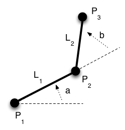
Here, P2 is defined as “rotate by a and then translate by L1 in that frame of reference. P3 is defined as “rotate by b from the frame of reference of P2 and then translate by L2 in that frame of reference.” Based on this, we could calculate:
matrix rot1 = ...;
matrix trans1 = ...;
matrix rotAndTrans1 = rot1 * trans1;
p2 = rotAndTrans1 * p1;

matrix rot2 = ...;
matrix trans2 = ...;
matrix rotAndTrans2 = rotAndTrans1 * rot2 * trans2;
p3 = rotAndTrans1 * p1;
Because multiplying “on the right” is the same as “add this transformation in local coordinates”, we can calculate the cumulative matrix for p3 by taking the intermediate matrix for p2 and applying additional transformations to it. This is the kind of thing that we would have done in OpenGL ES 1.x by pushing the current matrix, doing some additional transformations, then popping the previous matrix – the additional transformations would be applied “on top of” transformations that had already been performed. If you tried to “think this out” in “global” coordinates, it’s really tough – it’s much easier to think in terms of local coordinates.
Now park that fact away, and let’s look at matrix construction.
You will probably find thousands of references to the fact that a matrix like this:
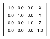
produces a translation by the amount (X,Y,Z). So, in your code, you want a translation by (5,2,1), and thus you write the following:
float translationMatrix[] =
{
    1.0, 0.0, 0.0, 5.0,
    0.0, 1.0, 1.0, 2.0,
    0.0, 0.0, 1.0, 1.0,
    0.0, 0.0, 0.0, 1.0
};
You construct your rotation and scaling matrices using similar formulas, and you try to combine them the way I talked about earlier. And they don’t work. Being desperate (or able to figure out what’s going on from what shows on the screen), you try reversing the order of the matrix multiplications, and suddenly everything works as expected. So you say to yourself – “This guy’s got it completely backward.”
Nope, I’m afraid you still do, and this is one of the huge problems with some of the tutorials “out there.”
OpenGL ES internally expects matrices to be in “column major order,” which means that the second entry in the array representing the matrix is “first column second row” not “first row second column.” The order of the matrix elements is:
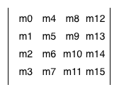
Thus, by writing the code above, you actually, from OpenGL ES’s point of view, defined the matrix:
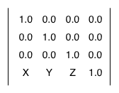
which is the “transpose” of the matrix you wanted. But, by one of those quirks of mathematical fate, if you transpose two matrices and exchange their order when multiplying, you get the same effect as multiplying the un-transposed matrices.
Thus, there are some tutorials out there that multiply matrices in the “wrong” order, but are saved by the fact that they also construct them the “wrong” order.
The second aspect you have to watch out for, however, is that “standard OpenGL,” by which I mean the non-ES version used on desktops, actually allows the use of either column-major or row-major matrices. When you pass a matrix into non-ES OpenGL (usually on its way to a shader), there is a parameter that allows you to specify the format of the matrix (column-major or row-major), and if you pass in a row-major matrix, OpenGL “takes care of it” for you. Thus, for non-ES code, it’s perfectly legal to use row-major matrices. (The original IRIS GL on which OpenGL was based, actually preferred the row-major order.) Not so in the ES version – this was one of the “simplifications” that was put in for mobile devices when the OpenGL ES spec was created.
If you want to keep your sanity, my own personal recommendation is that if you can, instead of creating the matrices yourself, you use a library such as GLM. This library stores all its matrices and vectors in exactly the format that the OpenGL shaders expect, which means that you can do matrix and vector math exactly the same way either in your application code (using GLM) or in the shader (using OpenGL’s implementation). They provide convenience methods for generating translation, rotation and scaling matrices, as well as for constructing the “view” and “projection” matrices.
Now back to our regularly-scheduled program. I mentioned earlier that there were four different matrices we had to worry about.
We’ve seen the tricks to constructing the “model” matrix. Assuming you defined your objects around the global origin (which is typically the case if you use a tool like Blender or one of its cousins) then to draw that object somewhere in 3-space you construct a matrix with the correct translations, rotations and scalings, and then give that to OpenGL as the model matrix before you draw the original points. By combining the matrix with the vertices in the vertex shader, they will appear properly in 3-space.
The view matrix is almost identical to the model matrix in concept, except reversed. For example, if you move your eye to the right, the effect is exactly the same as if you kept your eye fixed, and moved everything else in the world to the left.
The engines don’t move the ship at all. The ship stays where it is and the engines move the universe around it.
– Futurama
(Yes, I cribbed that from http://www.opengl-tutorial.org/beginners-tutorials/tutorial-3-matrices/, but it was too perfect.) (And I do watch Futurama, so I remember the quote.)
Trying to remember this backward-ness is a bit brain-numbing, but fortunately there are “helper methods” in most OpenGL math packages (including GLM) that will build this matrix for you by letting you specify where the “eye” is and where its “line of sight” is. The same is true for the projection matrix.
Because of the duality between the model matrix and the view matrix, it’s extremely rare that you actually need to deal with just one of them. Instead, you almost always deal with the product of the two – the “model view matrix.” Assuming you’re using column-major matrices, the correct means of computing this is
matrix model_view = view_matrix * model_matrix;
Remembering our matrix ordering, and thinking in “global coordinates,” this implies that when a point is transformed via the model_view matrix, the model matrix is applied first (thus putting the point in its correct position in 3-space), and then the view matrix is applied (getting the 3-space point into our “eye space.”) This order obviously makes intuitive sense.
Similarly, you generally use the product of the model, view and projection matrices when transforming points to (effectively) screen coordinates in your vertex shader.
matrix model_view_projection = projection_matrix * view_matrix * model_matrix;
vec4 transformedVertex = model_view_projection * input_vertex
Remembering the “right to left rule,” because these are “global” matrices, this says that we transform vertices by the model matrix to put them in 3-space, then by the view matrix, to get them relative to the eye, then by the projection matrix to get them onto the screen, which is what we want. Again, I’ve seen tutorials that show the multiplication as being in the other order (i.e. model then view then projection) but if you dig into them, they typically actually have row-major matrices instead of column-major matrices.
For some shaders, all you need is the “model view projection matrix.” If you are doing lighting calculations, however, you frequently need the “model view” matrix itself, since it will let you compute where lights in the scene are from the point of view of the eye. While you could send the individual matrices to the shaders and let them construct the combinations, if you have many vertices per object, it’s usually more efficient to calculate the matrices in the application program and pass them into OpenGL already set up.
Finally, the “normal” matrix. It turns out that if you’re doing anisotropic scaling (i.e. scaling along one coordinate more than another), you have to compute normal vectors differently from “corner of my triangle” vectors. The diagram below shows the problem
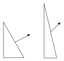
As you can see, if we scale the normal vector the same way as the image, it no longer ends up perpendicular (i.e. “normal”) to the edge. To fix this problem, we need a different matrix, usually referred to as the “normal matrix” to process normal vectors.
One calculates the normal matrix as follows:
- Take the 4×4 model view matrix, and extract the 3×3 upper left corner
- Invert the matrix
- Transpose the result
This gives us the matrix we need. The second two steps aren’t required if you aren’t doing anisotropic scaling, since with uniform scaling they result in (effectively) the same original value for the normal matrix. One thing you do have to watch out for, however, is that if you are doing any scaling, simply multiplying the original normal vector by the normal matrix may result in a vector that’s not of unit length, which will usually mess up your lighting calculations. Thus, you may have to “normalize” (different meaning of “normal”) the normal vector afterwards so that it is of unit length. This is frequently done in the fragment shader, since interpolated normal vectors are also frequently of non-unit length, and there’s no sense in doing the normalization calculations more than once.
As I indicated, I recommend you read http://www.opengl-tutorial.org/beginners-tutorials/tutorial-3-matrices/ if you want to get the model, view and projection matrices a bit more firmly embedded in your head. Once you have them calculated, handing them over to OpenGL is then pretty simple – you
- Define a shader variable for each
- Bind the shader variable to a
uniformID as part of building the program using your shader - Pass the matrix values to OpenGL using
glUniformMatrixXXX
The model-view-projection matrix and model-view matrix are both 4×4’s, while the normal matrix is a 3×3, so you use glUniformMatrix4fv for the first two, and glUniformMatrix3fv for the normal matrix.
Hopefully that helps a little with matrix math in your application…